Hi....I'm Pat
A little history about me:
30 years old, been a gearhead all my life....built a few hotrods, then a few road race cars, now I play with jet boats. I spent about 7 years working as a dealer tech at Toyota and GM and I've assembled my share of engines. In the last few years on my own stuff, I've learned tons. I've tooled up in measuring equipment and have realized one of 2 things.....A: I'm way to picky or B: Everyone I sub work out to is a hack.
I've got a nice little 20x32 shop set up at the house with a Mill, Lathe, Mig, Tig, 80gal compressor, more stuff than I know what to do with. I'm mostly a hobbyist. Every time I've paid someone to do a job for me, they screw it up or don't do it to the standards I'm looking for....most recently, cylinder head work. I've been shopping craigslist and ebay and have aquired a valve grinder, seat grinder, ball drive tooling for the mill, and a bunch of measuring tools to tell me how screwed up of a job I end up doing. In researching doing my own headwork...I stumbled across the hundreds of different serdi/newen style cutter profiles...how to choose which seat profile?.....which prompted me to build a flow bench. So the research started.....
I've got my heart set on using shop vacs for the time being simply because I've got access to quite a few of 'em and they won't cost me a dime for the time being, plus, I've got 4 different 20A 120V circuits in the shop so I can run a few of 'em at a time.
Questions:
I hate particle board. Is there any specific reason, aside from the pre-sealed melamine aspect of it as to why one would use melamine over some nice plywood? The HomeDepotMotorsports down the street has some nice double sanded 7 ply 3/4 stuff that looks almost furniture grade for $23/sheet....I was planning on using this stuff, then seal it with polyester resin inside and out.
Orifice plates....I found a formula a few months ago that gave a flow rate of a sharp edged orifice after taking into acct test pressure and surface area of the hole in the plate....cannot find that anymore. It probably doesn't matter in my case, since this is more of a comparative tool, but I'd like the numbers to be somewhat inline with industry standards rather than just looking at % of improvement (or the other way around).
I'm sure there will be more questions. I've purchased the plans from Bruce and while I won't follow them dead nuts, all of the concepts will be incorporated.
Thanks, this is a great site.
Flow Bench Newb with Questions
-
lbhsbz
- Posts: 3
- Joined: Wed Dec 29, 2010 2:39 pm
Flow Bench Newb with Questions
My flowbench sucks
-
blaktopr
- Posts: 622
- Joined: Sat Feb 20, 2010 9:27 pm
- Location: Central NJ
- Contact:
Re: Flow Bench Newb with Questions
Hello Pat and welcome aboard. I also feel your pain about subs. As for the plywood. It comes down to it's density. You will be screwing into the end. The plys can split. Also when screwing through the board to the end, it will crush. I used 3/4 treated ply for my wet attachment and motor box because I had it. The only thing I did differnt was I "dato-ed" the ends on a few board surfaces to give it 2 sides to seal. They were predrilled, glued, and screwed. The only problem was slight alignment problems even though strait edges were used to guide the router. Read through the forum and good luck on your project.
Chris Sikorski
Chris@wetflowtech.com
Totallywirednow.com
Chris@wetflowtech.com
Totallywirednow.com
-
coulterracn
- Posts: 450
- Joined: Wed Feb 24, 2010 5:44 am
- Location: Mississippi Gulf Coast
- Contact:
Re: Flow Bench Newb with Questions
Welcome to the forum Pat,
I used 3/4" arauco plywood and construction adhesive due to the humidity here along the Mississippi Gulf Coast. I painted the interior and exterior surfaces with Rustoleom spray paint.
I recommend following the plans from Bruce and using latex paint because it's much cheaper and less mess.
Ray
I used 3/4" arauco plywood and construction adhesive due to the humidity here along the Mississippi Gulf Coast. I painted the interior and exterior surfaces with Rustoleom spray paint.
I recommend following the plans from Bruce and using latex paint because it's much cheaper and less mess.
Ray
My Flowbench is better than their's
-
jfholm
- Posts: 1628
- Joined: Fri Feb 19, 2010 7:36 pm
- Location: Grantsville, Utah 45 min west of Salt Lake City
Re: Flow Bench Newb with Questions
Welcome aboard Pat!
I started out just building the chamber side of Bruce's plans and just splicing in 2 shop vacuums. They are Craftsman and one is 6 hp and the other 4.5 and I can easily pull 10" H2O through a SBC head. So if you could do more than all the merrier. Maybe you could take the vacuum motors out of the shop vacs and incorporate them into a full blown bench using the full plans.
I am in the process of building an eight motor bench and I am using plywood for what it is worth.
The picture is of the one I "threw" together in a weekend just to see if it would work. It is ugly but spot on. The new one will be much nicer looking.
John
You do not have the required permissions to view the files attached to this post.
-
Tony
- Posts: 1438
- Joined: Wed Mar 03, 2010 3:40 pm
- Location: Melbourne, Australia
Re: Flow Bench Newb with Questions
Hello Pat, welcome to the Forum.
Good top grade marine ply is usually a good deal more expensive than MDF, but if you can get it at the right price, it should be o/k. The only reservation I have might be screwing into the edge of a sheet may create splitting.
The main aim should be absolute structural strength, the forces of air pressure are enormous.
Twenty eight inches of test pressure is 1psi, or 1,296 Lbs per square yard, trying to burst or implode your bench. So whatever you decide to do regards construction materials, keep in mind the very large forces involved.
As for orifice plates, there is enough info here on the Forum to make something up yourself at least for some initial trials and testing. Or Bruce can supply something with known accuracy at very reasonable cost.
Also known as the infamous "Warpspeed" on some other Forums.
-
lbhsbz
- Posts: 3
- Joined: Wed Dec 29, 2010 2:39 pm
Re: Flow Bench Newb with Questions
Well, This is how far I got yesterday.
the box is all built out of 21/32 (why they can't just make it 3/4" I don't know) cabinet grade plywood that I got at HD for $23/sheet. 2 1/2 sheets total. I ripped some straight kiln dried 2x4s down to 1 1/2" x 1 1/2" to use in all the corners. All of the joints were predrilled, glued and screwed, then the 1 1/2" x 1 1/2" backers added, glued and screwed, then I caulked all of the seams/corners. I got the first coat of paint on the inside and filled all of the exterior screw holes so I can sand it and it'll look good.
For the manometers, I'm using the same plywood and 1/4" or so clear vinyl tubing for the time being, I'll router grooves into the plywood to keep the tubing straight, and use some plexi to hold it in place. Gotta head back to HD today and see what they've got for tubing/fittings, and finish up painting.
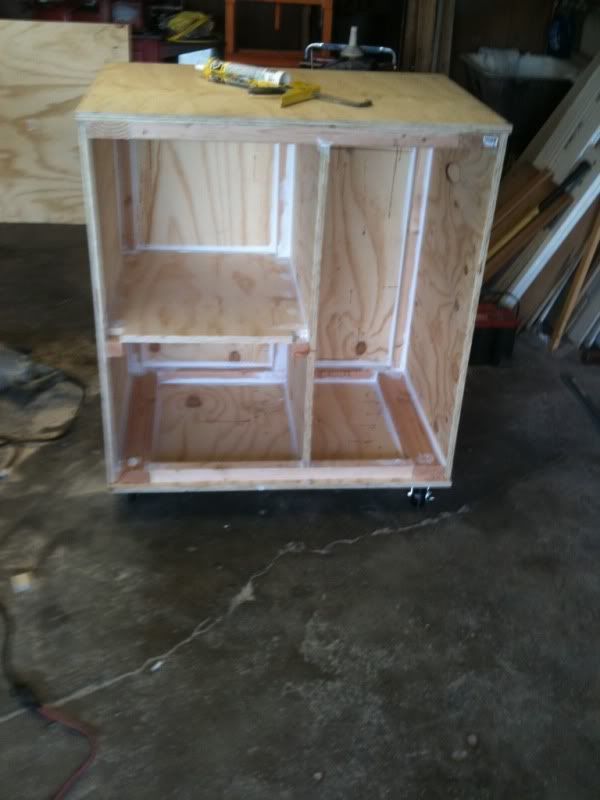
For now, I've got a 4" round hole cut for the orifice plate and four 4" round holes cut in the verticle divider to my "air source chamber". Based on the PTS drawings, this should be adequate. If not, I'll make a few more.
One more quicky question....
I've been browsing all kinds of designs on the interweb and a couple of them I see call for a piece of "laminar flow grid" upstream and downstream of the orifice plate, whereas the PTS drawings seem to recommend a piece of plywood baffle.
Both styles seem to use sharp edged orifice plates which if I understand things correctly, rely on laminar flow to be accurate. Which is the way to go and more importantly, why? Or it does it make any difference whatsoever?
the box is all built out of 21/32 (why they can't just make it 3/4" I don't know) cabinet grade plywood that I got at HD for $23/sheet. 2 1/2 sheets total. I ripped some straight kiln dried 2x4s down to 1 1/2" x 1 1/2" to use in all the corners. All of the joints were predrilled, glued and screwed, then the 1 1/2" x 1 1/2" backers added, glued and screwed, then I caulked all of the seams/corners. I got the first coat of paint on the inside and filled all of the exterior screw holes so I can sand it and it'll look good.
For the manometers, I'm using the same plywood and 1/4" or so clear vinyl tubing for the time being, I'll router grooves into the plywood to keep the tubing straight, and use some plexi to hold it in place. Gotta head back to HD today and see what they've got for tubing/fittings, and finish up painting.
For now, I've got a 4" round hole cut for the orifice plate and four 4" round holes cut in the verticle divider to my "air source chamber". Based on the PTS drawings, this should be adequate. If not, I'll make a few more.
One more quicky question....
I've been browsing all kinds of designs on the interweb and a couple of them I see call for a piece of "laminar flow grid" upstream and downstream of the orifice plate, whereas the PTS drawings seem to recommend a piece of plywood baffle.
Both styles seem to use sharp edged orifice plates which if I understand things correctly, rely on laminar flow to be accurate. Which is the way to go and more importantly, why? Or it does it make any difference whatsoever?
My flowbench sucks
-
Tony
- Posts: 1438
- Joined: Wed Mar 03, 2010 3:40 pm
- Location: Melbourne, Australia
Re: Flow Bench Newb with Questions
Yes it makes a difference.lbhsbz wrote: Both styles seem to use sharp edged orifice plates which if I understand things correctly, rely on laminar flow to be accurate. Which is the way to go and more importantly, why? Or it does it make any difference whatsoever?
To understand why, you need to visualize how stable stagnant air flows into a round hole set into a flat surface.
It does not rush straight towards the hole from all directions, as most of us might intuitively think.
What happens is, the accelerating air creeps in radially from all around the flat surface, and spills over the edge into the hole. Very little air travels straight down towards the hole from directly above.
If you point a powerful directional air source (such as a compressed air nozzle) straight at a measurement orifice, it just FORCES turbulent air through, and the orifice acts in a completely unnatural way, and it introduces measurement errors.
So blasting air axially at a measurement orifice, either by locating it in a pipe, or fitting "flow straighteners" right in front of an orifice, is performing an UNNATURAL ACT upon the up stream air.
Let it flow unmolested how it wants to flow..............
A far better way is to place a flat shielding baffle plate directly some distance directly in front of the orifice, and allow the air to flow naturally in from the sides evenly all the way around the orifice with minimal obstruction. This all assumes a sufficiently large settling air volume up stream of the orifice.
When you power up your bench, get some wool or string and see how the wool follows the air through into the orifice. You will quickly see the effect of this curious accelerating radial inflow into the hole.
Also known as the infamous "Warpspeed" on some other Forums.
-
lbhsbz
- Posts: 3
- Joined: Wed Dec 29, 2010 2:39 pm
Re: Flow Bench Newb with Questions
great explanation...thanks.
My brain hurts trying to figure out the inclinded manometer....
Here's where I'm at.
I wanted better resolution than a 30° incline gives you, so I doubled that and went for a 24" linear x 6" rise, which turned out to be 14.47°, and gave me about 4:1 resolution instead of the 2:1 that I would get with a 30° scale....This was all fine and dandy until I realized that I have to take surface area/level drop of the reservior into account to get an accurate measurement from the manometer.
My res has ID of 1.940", which puts the surface area at 2.540 square inches. My manometer tubing has an ID of .177", which makes the SA .02459 square inches. For each 1" of linear fluid travel in the tube, my reservior level will drop 0.008" based on my math, which is an error of about .032/1" WC. This will give a total error of 0.192" (about 3/32) over a 24" scale. According to the spreadsheet, this is less than 0.5" error.
The question....do I care? I suppose I could use a 4" diameter reservior such that the fluid level drop over my 24" scale would be only .046, so my error would be only .0078" / 1" WC.
The objective here is to try and use a 1" incriment rule for my scale and simply divide by 4. What level of error is acceptable?
Yeah, I'm about ready to just nut up and by the electronic deal but I'll have to buy a laptop too....funny how things snowball like this.
Edit: It just occured to me that the floor in my garage is not level, and unless I want to break out my machinist's level and shim stock every time I use the bench, this is all probably a moot point.
My flowbench sucks
-
Tony
- Posts: 1438
- Joined: Wed Mar 03, 2010 3:40 pm
- Location: Melbourne, Australia
Re: Flow Bench Newb with Questions
You don't need to even know or measure what the angle of an incline is.
All that matters is the difference in height between the high end and the low end.
Six inches of pressure will push the fluid along the incline as far as it needs to go until it reaches the final height of six inches pressure differential between well and fluid column.
You don't need to worry about the well either !!
With no pressure, set the zero point on your manometer scale by adding or removing fluid.
Apply (for example) six inches of differential pressure and tilt your incline so the fluid just reaches the 100% mark on your incline.
Now suppose the fluid drops half an inch in the well, by raising the high end of the manometer to only five and a half inches, it will then read zero to six inches pressure differential on your 0% to 100% scale.
Make the manometer tube any length that is convenient for marking off the graduations, the longer it is, the easier it will be to read. Obviously the tube must be dead straight !
If you have a very uneven floor, a very low angle of slope will be very sensitive to changes in bench position. Best bet is to screw the sloping manometer to a solid wall above the bench.
Also known as the infamous "Warpspeed" on some other Forums.