Hi Bruce,
I have an Ender 3 (non Pro version) the print bed was just capable of printing the larger components for this project.
One thing I didn't appreciate when starting this project was how long it takes to print something. Some of the larger items had print times of over 24 hours! Its good job I've got a lot of spare time right now.
The printed items seem fairly robust and for my use as a hobbyist I think they'll be fine. If the parts were intended to be used routinely, in a head shop for example, I would consider a stronger filament type maybe ABS.
For you paddle wheel swirl meter you could print the whole cylinder with the right bore diameter and length and include all the bearing support structure.
Tumble meter
-
Brucepts
- Site Admin
- Posts: 1852
- Joined: Fri Jan 08, 2010 3:35 pm
- Location: Pennsylvania
- Contact:
Re: Tumble meter
3d printing is all new to me!
Looked at the Ender 3 but settled on the 5 Pro since it had some upgrades already and got it on the Spring Sale for what I thought was a good price.
My problem is, I have a drafting background but only in 2d and I need to get my head-around drawing in 3d What I really need is to just sit down and teach myself but can never find the hours required to get that done right now. My CAD software is capable of exporting .STL files but I have to draw them first.
After seeing what you came up with in your project it has sparked my curiosity though!!
Looked at the Ender 3 but settled on the 5 Pro since it had some upgrades already and got it on the Spring Sale for what I thought was a good price.
My problem is, I have a drafting background but only in 2d and I need to get my head-around drawing in 3d
After seeing what you came up with in your project it has sparked my curiosity though!!
Bruce
Who . . . me? I stayed at a Holiday in Express . . .
Who . . . me? I stayed at a Holiday in Express . . .
-
varnish1
- Posts: 10
- Joined: Tue Oct 03, 2017 1:38 pm
Re: Tumble meter
A comparison of flow induced tumble motion of a standard and a modified Mazda MX5 BP05 cylinder head's intake port.
The flow and tumble were measured, the port was modified (basic short side and chamber work) and the flow and tumble were remeasured.
Cylinder head flow and tumble test equipment and test procedure:
To measure the tumble, the cylinder head was positioned at 90° to the normal orientation, with the intake ports to the left this meant the manifold inlet was facing downwards. The ducting to the flowbench turns through 90° which allows the mixture motion to be measured at the swirl meter.
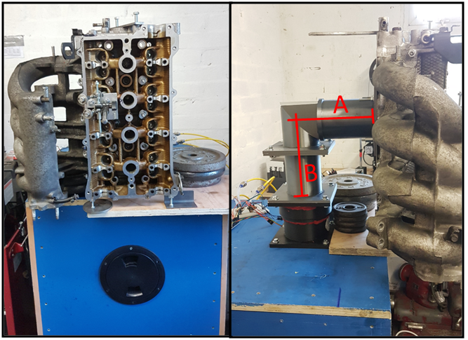
Cylinder head adapter geometry:
Bore (mm) 83 (1x Bore)
Length (mm) section A: 180 (2.17x Bore)
Length (mm) section B: 180 (2.17x Bore)
Test conditions:
7 kPa test depression
Intake manifold fitted (throttle removed)
Radius fitted to entry of intake manifold (in place of throttle body)
Test procedure:
Measurements taken at 1mm valve lift increments
Data averaged over 20 seconds
Valve opened to lift of L/D = 0.3 (10mm)
Test results:
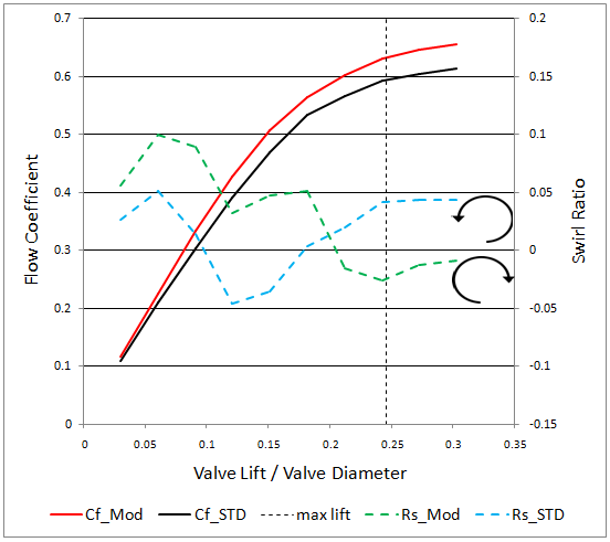
Flow coefficient and Swirl Ratio
The direction of tumble rotation reversed during the test. Anticlockwise rotation gave a positive Swirl Ratio, clockwise gave a negative Swirl ratio. The Flow coefficient is a discharge coefficient but uses the inner valve seat diameter (measured at the bottom of the 45° seat cut) instead of the valve curtain area. Dotted black line shows the maximum valve lift.
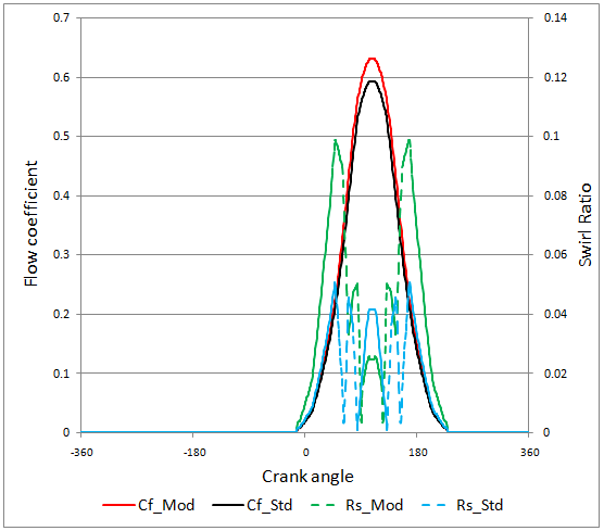
Flow coefficient and Swirl Ratio by crank angle
Same data as above but plotted by crank angle. I have ignored the change of swirl direct and given all swirl a positive sign to make calculations easier.
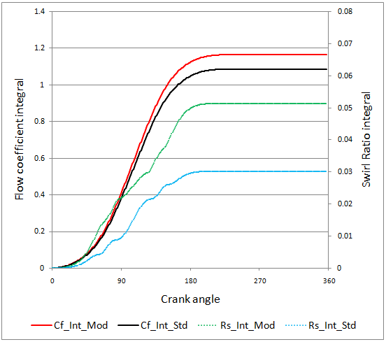
Integrated Flow coefficient and Swirl Ratio
Integral of the above data. The improved flow and swirl of the modified port are quite apparent in this chart.
Modified port performance:
Swirl Ratio [Rs] 0.077
Non-Dimensional Swirl Ratio [NDRs] 0.019
Mean Flow coefficient [Cf_Mean] 0.551
Mach Index [Mi] 0.419
Standard port performance:
Swirl Ratio [Rs] 0.052
Non-Dimensional Swirl Ratio [NDRs] 0.012
Mean Flow coefficient [Cf_Mean] 0.513
Mach Index [Mi] 0.449
The flow and tumble were measured, the port was modified (basic short side and chamber work) and the flow and tumble were remeasured.
Cylinder head flow and tumble test equipment and test procedure:
To measure the tumble, the cylinder head was positioned at 90° to the normal orientation, with the intake ports to the left this meant the manifold inlet was facing downwards. The ducting to the flowbench turns through 90° which allows the mixture motion to be measured at the swirl meter.
Cylinder head adapter geometry:
Bore (mm) 83 (1x Bore)
Length (mm) section A: 180 (2.17x Bore)
Length (mm) section B: 180 (2.17x Bore)
Test conditions:
7 kPa test depression
Intake manifold fitted (throttle removed)
Radius fitted to entry of intake manifold (in place of throttle body)
Test procedure:
Measurements taken at 1mm valve lift increments
Data averaged over 20 seconds
Valve opened to lift of L/D = 0.3 (10mm)
Test results:
Flow coefficient and Swirl Ratio
The direction of tumble rotation reversed during the test. Anticlockwise rotation gave a positive Swirl Ratio, clockwise gave a negative Swirl ratio. The Flow coefficient is a discharge coefficient but uses the inner valve seat diameter (measured at the bottom of the 45° seat cut) instead of the valve curtain area. Dotted black line shows the maximum valve lift.
Flow coefficient and Swirl Ratio by crank angle
Same data as above but plotted by crank angle. I have ignored the change of swirl direct and given all swirl a positive sign to make calculations easier.
Integrated Flow coefficient and Swirl Ratio
Integral of the above data. The improved flow and swirl of the modified port are quite apparent in this chart.
Modified port performance:
Swirl Ratio [Rs] 0.077
Non-Dimensional Swirl Ratio [NDRs] 0.019
Mean Flow coefficient [Cf_Mean] 0.551
Mach Index [Mi] 0.419
Standard port performance:
Swirl Ratio [Rs] 0.052
Non-Dimensional Swirl Ratio [NDRs] 0.012
Mean Flow coefficient [Cf_Mean] 0.513
Mach Index [Mi] 0.449
-
Brucepts
- Site Admin
- Posts: 1852
- Joined: Fri Jan 08, 2010 3:35 pm
- Location: Pennsylvania
- Contact:
Re: Tumble meter
Somehow I missed the followup posts to the testing on this project!
Thanks for sharing them with us
Thanks for sharing them with us
Bruce
Who . . . me? I stayed at a Holiday in Express . . .
Who . . . me? I stayed at a Holiday in Express . . .
-
huw
- Posts: 11
- Joined: Sun Jan 20, 2013 7:00 pm
- Location: West Wales, UK
Re: Tumble meter
Some interesting and pertinent comment there. Oh to have unlimited time in which to measure, test, modify, repeat. Sadly, without this I agree it will be difficult to quantify any gains. BUT, looking for gains no-one else has found is the goal is it not?1960FL wrote:Please don't take this the wrong way as i am trying to give direction to your thoughts on the subject and expected outcome of your hard work and time relating to TQ & HP gains at the rear wheel. In today's performance world a cylinder head porters work is only as valuable as his data bank a person like Darin Morgan is so competent at what he does because of his history and the data he has to go with it. Not only flow data but every spec relating to the heads he has done and all the dyno and tune data to go with it. He has spent a lifetime in engine R&D and has that in his pocket, he can say if i do this i expect to see this on the dyno. Most of us here in the hobby world are lucky to have a flowbench and the time to tinker on some heads on the weekend in hope our beloved hot rod goes faster down the track, around the track etc. As tony said there is relay no known tangible data that relates X swirl with Y HP gain or tumble at that. You have to ask yourself how do i deal with each of the variables in the test scenario? pick swirls you have clockwise or counter clockwise? slow, medium or fast? you have diverging swirl, one that twists toward the piston or one that is flat at the combustion chamber. Where do you measure it? or do you build a fixture that allows the measurement of swirl at incremental points moving away from the deck until you reach the full stroke length away? what does any of this mean? and what is the end goal? better mixture propagation? better thermal balance in the chamber? I personally think these are all good ideas but unless you have a repeatable methodology and system that you can collect data at each point of a test, make changes, dyno, validate and repeat i am not sure your really getting anywhere. You need a single cylinder Mule engine on a small dyno and your flowbench with the above derived tools, methodologies and data logging to start to make any sense of what one might have done in making the air move a specific way. This is in no way like Porting for Flow where we can look at know data points for our application and at least know what to expect from our changes and when we have gone to far.
I admire you for your ambition but i might also suggest your knowledge may advance faster with the simple implementation of wet flow where you can see what changes you made in the system quickly and compare one cylinder to the next for consistency.
I look forward to following your progress, as for tumble one could easily make a seesaw type devise that uses calibrates springs and linear potentiometers for output then have the ability to be lifted in the bore and rotate 180° to sweep at incremental steps. For beginning calibration you could use a fixed orifice at distance x to the paddle as you increase air pressure your impact goes up and correlates to your output reading this could be a simple variable voltage.
output to arduino. Or a more simple approach is you make a similar apparatus that instead has a Pito Tube at each end and you record that data ??
Just my thoughts
Rick.
-
huw
- Posts: 11
- Joined: Sun Jan 20, 2013 7:00 pm
- Location: West Wales, UK
Re: Tumble meter
There is so much black magic about swirl/tumble and it’s effectiveness, whether it’s how and where it’s measured, to how effective it is - does low lift swirl trump high lift swirl, given the actual gas flow is likely to be lower in this phase, does it matter if swirl reverses as lift increases - given the gas would need time to slow, stop, and reverse - would it have time? Maybe at low rpm??
A single cylinder on an engine Dino would seem to be the way forward for testing, otherwise it’s guessing and racing...
A single cylinder on an engine Dino would seem to be the way forward for testing, otherwise it’s guessing and racing...