I'm interesting in measuring the tumble on a 4V head.
I've seen a lot of information on, and commercial examples of, swirl meters. But instruments specifically for tumble measurement seem harder to come by.
The only example I've seen is by FEV here:
http://magazine.fev.com/en/fev-customiz ... stigation/
I see set ups using swirl meters with the head turned through 90°, like the performance trends product.
I don't think I like this method though, the alignment could be difficult get right every time.
http://performancetrends.com/tumble_fixture.htm
I think I prefer the torque impulse style of meter, such as this cussons unit, over the paddle wheel or spinning style of meter:
https://www.cussons.co.uk/products/mari ... wirl-meter
So, the question is:
Has anyone used a meter specifically for measuring tumble?
If you had to build one, how would you go about it?
Tumble meter
-
Tony
- Posts: 1438
- Joined: Wed Mar 03, 2010 3:40 pm
- Location: Melbourne, Australia
Re: Tumble meter
There are two fundamental problems here.
Its difficult to define what is actually being measured, and there are no recognised engineering units to measure in.
Any figure you come up with cannot be compared to to anything anyone else has measured, and there are no calibration standards.
Its difficult to define what is actually being measured, and there are no recognised engineering units to measure in.
Any figure you come up with cannot be compared to to anything anyone else has measured, and there are no calibration standards.
Also known as the infamous "Warpspeed" on some other Forums.
-
varnish1
- Posts: 10
- Joined: Tue Oct 03, 2017 1:38 pm
Re: Tumble meter
Heywood gives some information on swirl ratio and how to calculate it from either paddle wheel angular velocity or measured torque. I would be using these calculations.
What isn't covered by Heywood (although it's been a while since I've read it, so I may be mistaken) is the reference plane for the measurement, i.e. the distance from the head to the point of swirl measurement. I'll likely use 1.5x Bore.
Having a standardised swirl measurement would be great, but as I would have no data to compare my own measurements to (I've never seen any tumble measurements published for this cylinder head) I don't see this being an issue.
-
Brucepts
- Site Admin
- Posts: 1852
- Joined: Fri Jan 08, 2010 3:35 pm
- Location: Pennsylvania
- Contact:
Re: Tumble meter
Simple DC motor attached to a paddle wheel, measure +/- rotation and voltage generated.
You do not have the required permissions to view the files attached to this post.
Bruce
Who . . . me? I stayed at a Holiday in Express . . .
Who . . . me? I stayed at a Holiday in Express . . .
-
varnish1
- Posts: 10
- Joined: Tue Oct 03, 2017 1:38 pm
Re: Tumble meter
Hi Bruce,
I remember building something similar about 10 years ago. Probably inspired by those very some photos you've posted.
But I've made my mind up and I'm a lot more stubborn than I was 10 years ago. I want to build a torque measuring swirl/tumble meter.
Looking at some of the commercially available units I see AVL sell a 3D flow straightener combined tumble and swirl meter. More info here:
https://www.avl-tippelmann.com/theory.html
I found a picture of the AVL swirl meter line up:
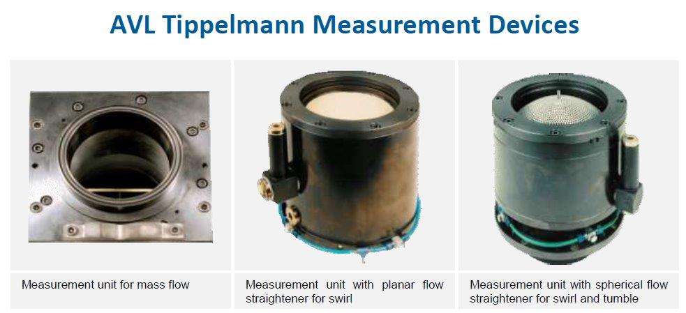
With the AVL 3D system, I have no idea if there's one or two torque measurements. One for radial swirl (tumble) and another one for axial swirl or just one for axial swirl?
Also AVL have repeated what Tony said so succinctly in the most pedantic and long winded way possible.
I remember building something similar about 10 years ago. Probably inspired by those very some photos you've posted.
But I've made my mind up and I'm a lot more stubborn than I was 10 years ago. I want to build a torque measuring swirl/tumble meter.
Looking at some of the commercially available units I see AVL sell a 3D flow straightener combined tumble and swirl meter. More info here:
https://www.avl-tippelmann.com/theory.html
I found a picture of the AVL swirl meter line up:
With the AVL 3D system, I have no idea if there's one or two torque measurements. One for radial swirl (tumble) and another one for axial swirl or just one for axial swirl?
Also AVL have repeated what Tony said so succinctly in the most pedantic and long winded way possible.
These kinds of swirl measurement devices are based on the idea to place a functionally shaped solid body pivot mounted in the flow, measure the rotational speed and draw a conclusion concerning the quantity of interest (swirl or tumble). This approach could only be successful if the rotation axis of such devices were congruent with the swirl axis, the swirl were homogenous (“rigid disc rotation”), the device could cover the whole cross section and the retardation by friction could be excluded or quantified – none of which is realistic. The additional assumption that flow components are conserved over long distances and even through changes of direction imposed by the piping – which would be essential for correct measurements using a T-piece – is at least rather optimistic. In modern equipment such devices should only be used to assure compatibility with existing databases.
-
1960FL
- Posts: 1338
- Joined: Fri Jan 08, 2010 10:36 pm
- Location: Maryland
Re: Tumble meter
Please don't take this the wrong way as i am trying to give direction to your thoughts on the subject and expected outcome of your hard work and time relating to TQ & HP gains at the rear wheel. In today's performance world a cylinder head porters work is only as valuable as his data bank a person like Darin Morgan is so competent at what he does because of his history and the data he has to go with it. Not only flow data but every spec relating to the heads he has done and all the dyno and tune data to go with it. He has spent a lifetime in engine R&D and has that in his pocket, he can say if i do this i expect to see this on the dyno. Most of us here in the hobby world are lucky to have a flowbench and the time to tinker on some heads on the weekend in hope our beloved hot rod goes faster down the track, around the track etc. As tony said there is relay no known tangible data that relates X swirl with Y HP gain or tumble at that. You have to ask yourself how do i deal with each of the variables in the test scenario? pick swirls you have clockwise or counter clockwise? slow, medium or fast? you have diverging swirl, one that twists toward the piston or one that is flat at the combustion chamber. Where do you measure it? or do you build a fixture that allows the measurement of swirl at incremental points moving away from the deck until you reach the full stroke length away? what does any of this mean? and what is the end goal? better mixture propagation? better thermal balance in the chamber? I personally think these are all good ideas but unless you have a repeatable methodology and system that you can collect data at each point of a test, make changes, dyno, validate and repeat i am not sure your really getting anywhere. You need a single cylinder Mule engine on a small dyno and your flowbench with the above derived tools, methodologies and data logging to start to make any sense of what one might have done in making the air move a specific way. This is in no way like Porting for Flow where we can look at know data points for our application and at least know what to expect from our changes and when we have gone to far.
I admire you for your ambition but i might also suggest your knowledge may advance faster with the simple implementation of wet flow where you can see what changes you made in the system quickly and compare one cylinder to the next for consistency.
I look forward to following your progress, as for tumble one could easily make a seesaw type devise that uses calibrates springs and linear potentiometers for output then have the ability to be lifted in the bore and rotate 180° to sweep at incremental steps. For beginning calibration you could use a fixed orifice at distance x to the paddle as you increase air pressure your impact goes up and correlates to your output reading this could be a simple variable voltage.
output to arduino. Or a more simple approach is you make a similar apparatus that instead has a Pito Tube at each end and you record that data ??
Just my thoughts
Rick.
-
varnish1
- Posts: 10
- Joined: Tue Oct 03, 2017 1:38 pm
Re: Tumble meter
Hi Rick,
Thank you for your comments.
I think you may have made some assumptions about my motivations that are not correct.
There are no commercial or competitive aspects to this project. I do not intend to use the data to improve cylinder head design. I intend to measure and record the figures purely for my own interest.
I am very aware of the limitations of swirl and tumble measurements, but this does not overly concern me as the data produced by this project will be for my enjoyment only. The motivation was very much the same when I built my flow bench.
-
1960FL
- Posts: 1338
- Joined: Fri Jan 08, 2010 10:36 pm
- Location: Maryland
Re: Tumble meter
I see! Maybe you should reread my post a couple times, i make no assumptions on what drives you, i make assumptions on Data of which i like to collect and have a pretty good understanding of.varnish1 wrote:Hi Rick,
Thank you for your comments.
I think you may have made some assumptions about my motivations that are not correct.
There are no commercial or competitive aspects to this project. I do not intend to use the data to improve cylinder head design. I intend to measure and record the figures purely for my own interest.
I am very aware of the limitations of swirl and tumble measurements, but this does not overly concern me as the data produced by this project will be for my enjoyment only. The motivation was very much the same when I built my flow bench.
Again, if you were to build a tumble meter and collect data for your enjoyment and analyses i support you, but the data has NO value if the assumption of the results cannot be validated in some form of a performance metric.
I look forward to the topic and your contribution to the forum.
Rick
-
varnish1
- Posts: 10
- Joined: Tue Oct 03, 2017 1:38 pm
Re: Tumble meter
Update on my endeavor to collect valueless data  :
:
I have constructed an impulse style swirl meter from 3D printed parts (printed in PLA).
This swirl meter employs flow straightener or "honeycomb". A strain gauge mounted to a central shaft measures the force caused by the torque reaction produced when swirling air is straightened by the honeycomb.
The components are displayed below:
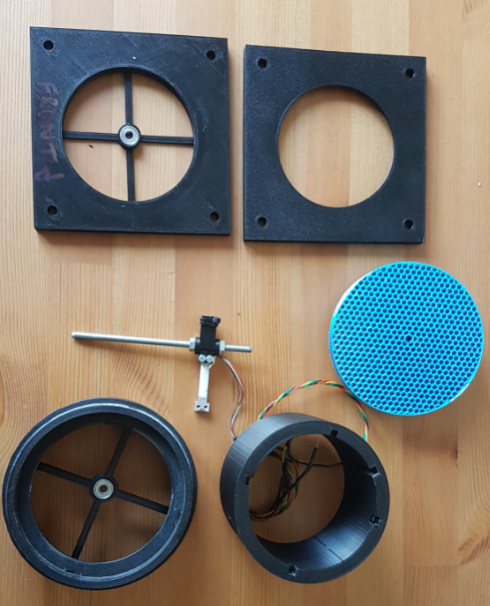
Here is the lower section of the meter without the honeycomb installed. The strain gauge is retained by the cylinder wall.
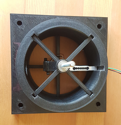
The complete meter with honeycomb and top plate:
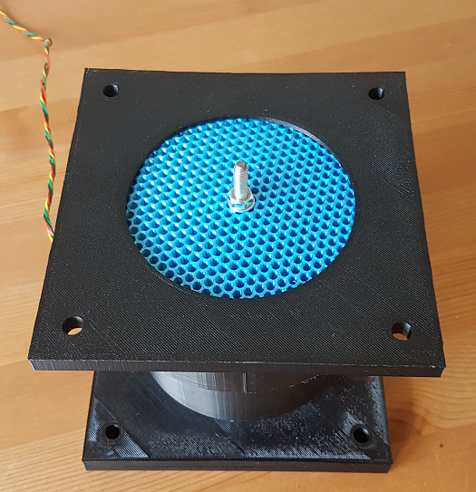
Swirl meter with calibration arm attached (the calibration process is similar to that used with an engine dyno):
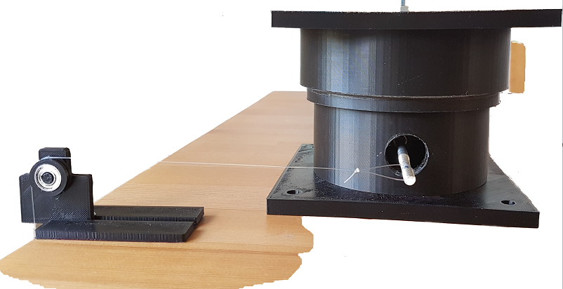
The electronics consist of a strain gauge (rated to 100g) and a HX711 load cell amplifier which is used in conjunction with an Arduino Uno.
I expect to have collected the flow and tumble data and have written a report with my findings by the end of next week.
I have constructed an impulse style swirl meter from 3D printed parts (printed in PLA).
This swirl meter employs flow straightener or "honeycomb". A strain gauge mounted to a central shaft measures the force caused by the torque reaction produced when swirling air is straightened by the honeycomb.
The components are displayed below:
Here is the lower section of the meter without the honeycomb installed. The strain gauge is retained by the cylinder wall.
The complete meter with honeycomb and top plate:
Swirl meter with calibration arm attached (the calibration process is similar to that used with an engine dyno):
The electronics consist of a strain gauge (rated to 100g) and a HX711 load cell amplifier which is used in conjunction with an Arduino Uno.
I expect to have collected the flow and tumble data and have written a report with my findings by the end of next week.
-
Brucepts
- Site Admin
- Posts: 1852
- Joined: Fri Jan 08, 2010 3:35 pm
- Location: Pennsylvania
- Contact:
Re: Tumble meter
Nice job!
I have an Ender 5 Pro on order and one of my projects is to make a vane/blade for the swirl setup I posted pics of from way back when. Just one of those projects I also want to play with for no specific reason other than to "do it" and justifying a 3d printer purchase
I have an Ender 5 Pro on order and one of my projects is to make a vane/blade for the swirl setup I posted pics of from way back when. Just one of those projects I also want to play with for no specific reason other than to "do it" and justifying a 3d printer purchase
Bruce
Who . . . me? I stayed at a Holiday in Express . . .
Who . . . me? I stayed at a Holiday in Express . . .