Using a differential pressure gauge to sniff out velocity

Place to add formulas. If you post a formula please make sure your abbreviations are spelled out so it avoids a lot of follow-up postings. I know a lot of abbreviations are common or taken to be common knowledge. Please be sure to checkout the new FAQ of common abbreviations.

Please post formulas in separate topics, do not add formulas to someone else's post unless it relates to the original post. Also in the topic line make a note of what your posted formula is about . Thanks
Post Reply
pcnsd
Posts: 31
Joined: Thu Nov 15, 2012 11:53 pm

Using a differential pressure gauge to sniff out velocity

Post by pcnsd »

Why? Because I find the stabilized output from my velocity probe to be too slow and I didn't want to spend the money to have an exhaust probe. Also the sniffer fits to areas the velocity probe cannot. The soft copper construction allows its shape to be modified repeatedly and the smaller profile provides less disturbance of the port flow.

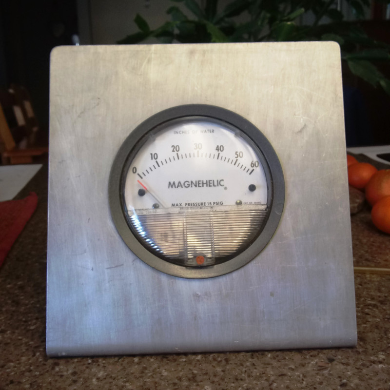
The gauge I'm using is a Magnehelic, 0-60 inches of water pressure gauge made by Dwyer. It is somewhat limited in resolution. I have yet to see pressures above 45" H2O while testing at 28" H2O. You should consider what test pressure you will be working at before purchasing. The gauges can be found used on Ebay for $30-$50.
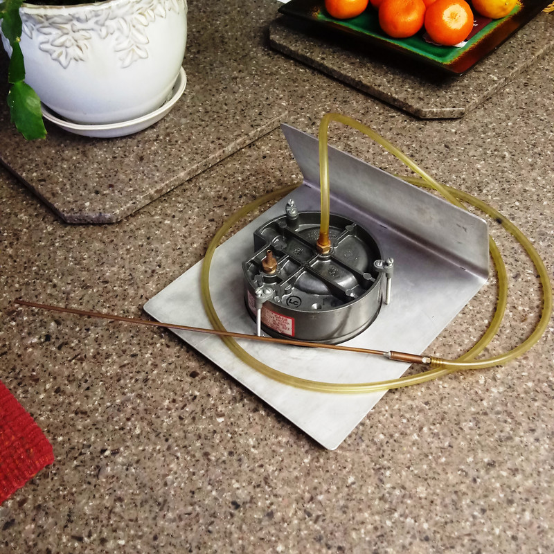
The sniffer is just 1/16" copper tubing soldered to 1/8" copper tubing with a 1/8 brass hose barb. The connection between the sniffer and gauge is 1/8" polyurethane tubing.The system can work for both Intake and Exhaust velocity evaluation. You need to switch the hose connection around on the gauge for exhaust testing. One side is always open to ambient pressure. If I ever find a proper light duty QD, I may go that route.

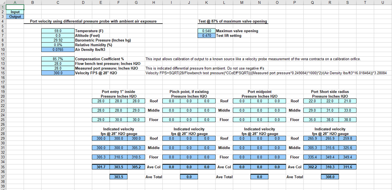
To calibrate the equation output, you need a velocity probe or you can trust my set up which was done at 28" H2O.
You adjust the Compensation Coefficient to reflect the same velocity output from the velocity probe. I do this in the vena contracta of the calibration orifice used during bench set up at 28" H2O.
Some pictures of what it looks like:
Image

Image

Picture of the spreadsheet:
Image
Velocity from pressure in port.xlsx
If you have any questions, I will attempt to respond.

Paul
You do not have the required permissions to view the files attached to this post.
Tony
Posts: 1439
Joined: Wed Mar 03, 2010 3:40 pm
Location: Melbourne, Australia

Re: Using a differential pressure gauge to sniff out velocity

Post by Tony »

Not sure if that method is valid ?

The airspeed indicator in a aircraft uses a pitot tube, with which we are all more or less familiar.
There is an impact port at the end, and one or more pinholes along the length to measure static pressure in the boundary layer.
By measuring the pressure difference (and adding some corrections) we can come up with an indicated airspeed figure.

Now an aircraft is flying through a more or less constant air pressure.
If you put the same probe into something like a cylinder head port, there is going to be quite a large pressure drop over the three or four inches of port length. As the static pressure holes will be located some distance behind the impact port, that might skew the differential pressure results.

The worst possible way to do it would be to just have an impact port and use outside ambient air pressure as the measuring reference.

If it were possible to push your probe right past the seat right into the combustion chamber, there would be 28 inches of vacuum (or pressure) in there, and there would be a massive airspeed indicated, which is really mostly just the static pressure difference being measured.
That cannot be right.
Also known as the infamous "Warpspeed" on some other Forums.
Post Reply