hello mr 2seater,
i have a thread on here using a dark side setup , it has a few numbers in it showing pressure drop etc ,have a look ..
http://www.flowbenchtech.com/forum/view ... ?f=8&t=519
regards
robert
From dark into the light?
-
ivanhoew
- Posts: 954
- Joined: Wed Feb 16, 2011 5:12 am
- Location: oxford ,england .
Re: From dark into the light?
medusa assembled..first drive
https://www.youtube.com/watch?v=zKMvQQm7Cn4&t=5s
https://www.youtube.com/watch?v=zKMvQQm7Cn4&t=5s
-
1960FL
- Posts: 1338
- Joined: Fri Jan 08, 2010 10:36 pm
- Location: Maryland
Re: From dark into the light?
This is sort of like the law of diminishing returns, The key here as Tony has mentioned is air stability the lesser the pressure the more the air entering or exiting the orifice can be subject to turbulence. For an orifice to be accurate/repeatable the air approaching the entry and moving through the orifice should be near laminar.This of course begs the question, how low can the Delta p be, using water manometers and expect reasonable accuracy? If I use the 2.68", 515cfm @ 28", plate from Bruce, are the standard pressure drop formulas usable for this application, such as 389cfn @ 16" and 275cfm @ 8". The exact numbers aren't important, only the two different range question.
What does all this mean, the lower the DP the more impact settling chamber size will have on the air passing through. My guess is you will want a lot more chamber with a 8” DP with smooth clean construction and a clean approach to the orifice.
Also remember at an 8” DP you are talking about an internal plate of around 4.125” needed to for 600CFM on top. This is now moving away from the standard plate size or a special THIN mounting fixture would be needed to reduce effects on air entering the plate.
These are all things Bruce , Tony and I discussed during Bruce’s designing of the PTS bench and to tell you the truth Bruce and I often converse and rehash the PTS design looking for improvement. The fact is we have three basic requirements in building a good flowbench, Human Energy, Electrical Energy & Money if you have none of the first you need more of the third, but neither will do you any good without the Electricity. So if you have machine shop & cabinet shop you can make everything and spend less.
2seater in your design I would suggest using Bruce’s plans to give you an idea of the orifice box side with the two settling chambers, build that under your counter top and as John said add the taps for you motor box. My suggestion is that you build your chambers out of 1” plywood and reinforce the corners so you can work your way to a higher test pressure bench design.
Rick
-
2seater
- Posts: 21
- Joined: Tue Mar 09, 2010 5:39 pm
- Location: Appleton, WI
Re: From dark into the light?
Thanks for the additional info. Water gauges will be used for now as income has been a casualty of the recent recession. The only reason I mentioned the 8" and 16" inclined scales is because they already exist, as well as the orifice plate. I do a have a couple of smaller ones for calibration purposes. I think I understand that the higher up the scale we go for testing, the less the background noise interferes. In that respect, only testing will give me a baseline for the maximum flow vs depression and I can plan from there. Not having used one yet, I can only surmise that the larger the volume of the chambers, the slower it will respond, but with the benefit of increased accuracy. Spherical or cylindrical shapes would be best for strength but are also much more dificult to work with. A welded frame won't be a problem when it comes time for that.
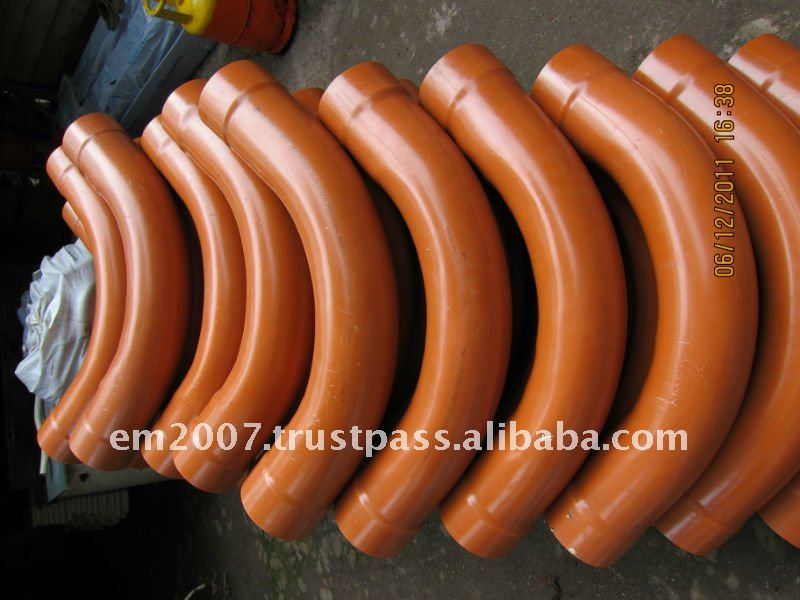
Oh, one more thing. The toothpaste tubing plumbing is a work of art. The whole thing should be framed. It's just so much more elegant than pvc.
Oh, one more thing. The toothpaste tubing plumbing is a work of art. The whole thing should be framed. It's just so much more elegant than pvc.
-
Tony
- Posts: 1439
- Joined: Wed Mar 03, 2010 3:40 pm
- Location: Melbourne, Australia
Re: From dark into the light?
Agree, Robert's bench is a masterpiece of originality and well thought out design.
In the above link to the building of that bench, the testing of the flow element pipework with it's required roughly ten pipe diameters, and smooth large radius bends, produced an overall pressure loss around the same as a typical orifice bench of similar flow range.
So neither type of bench has any great flow advantage given the same air blower.
Nothing really wrong with PVC.
Most people use storm water or waste water pipework and fittings which are designed to have very tight bends to go around and through walls and floors.
A better solution for a dark side bench might be large diameter PVC electrical conduit.
You can obtain this with smooth large radius bends for pulling heavy cables through.
The only complication is the electrical conduit sizes are not compatible with the plumbing sizes, so you cannot easily mix the two.
I would still prefer an orifice bench to a dark side bench, and the very best way to get started would be with a set of Forum flow bench plans. It is a well proven design which could readily be adapted to use the external blower box you already have.
Also known as the infamous "Warpspeed" on some other Forums.
-
ivanhoew
- Posts: 954
- Joined: Wed Feb 16, 2011 5:12 am
- Location: oxford ,england .
Re: From dark into the light?
gosh thanks chaps !
medusa assembled..first drive
https://www.youtube.com/watch?v=zKMvQQm7Cn4&t=5s
https://www.youtube.com/watch?v=zKMvQQm7Cn4&t=5s
-
2seater
- Posts: 21
- Joined: Tue Mar 09, 2010 5:39 pm
- Location: Appleton, WI
Re: From dark into the light?
I certainly have nothing against pvc. I use it a lot, from spud guns to pressurized brake bleeders. Hard to beat for ease of assembly. Beauty is not one of its attributes (IMHO). I did emergency vehicle plumbing in a previous lifetime, and friction loss was always a consideration. There are actually rules for what is allowed. Welded stainless steel piping certainly had an advantage over the old school threaded pipe fitings. Various elbows might be an interesting item to test. I have seen videos of flow in pipes, particularly around bends that look interesting. I know we used turning vanes on occasion where the direction change was unavoidably abrupt which proved to really help flow. Hold a screen from a mass air sensor under a stream of water and tilt the screen to change the flow direction. I was impressed by how far it can be tilted while maintaining the stream shape. I'm pretty sure there is an energy loss but no way to tell. I have never tested, but have read a fair amount about how much of a direction change air can follow and remain stable. It doesn't seem to be much.
-
2seater
- Posts: 21
- Joined: Tue Mar 09, 2010 5:39 pm
- Location: Appleton, WI
Re: From dark into the light?
I did put together the five gallon bucket orifice system I mentioned earlier. I used the "orifice flow in a pipe" by Del Segura to get an initial baseline flow rate for the 2.68" orifice of about 384cfm @ 16". The 200 cfm and 349 cfm plates were used as the test plates and I must admit I was surprised when the numbers lined up within a couple of percent on the first run. I tried the tests several times over a few days and they repeated very well. I tweaked the cd of the measuring plate to .628 and the numbers lined up almost pefectly, at both the 51.5% and 90% points. From what I have read, this is a valid way to correct the readings on a particular bench, is this correct?
I ran the bench with the 5" test hole open to get an idea of the max. flow available through the 2.68 orifice. My digital manometer indicated 33.9" maximum, or in the mid 500cfm range. This seems to be approximately in line with estimated max. capacity using the 3" pitot tube. During this test there was 3" depression at the test opening. I'm sure maximum flow would be considerably lower with a significant depression at the test port but I am looking for a valid way to size the orifice plate for high flow. For reference, I did run all motors wide opening using the 2.207"/349cfm plate and reached 36.5" depression and approx. 19" (not stable) across the 2.68". This would be in the 400 cfm range. It would seem something in the 425-450 cfm range @ 16" would be appropriate. Any suggestions?
All in all, I now understand why the vast majority have moved to the orifice system. When I checked some of my previous records of the same plates with the pitot tubes, they were all over the place. Not terrible; but high, low and in between. I do believe there is some cost in total flow capability, but the tradeoff is worth it.
-
Tony
- Posts: 1439
- Joined: Wed Mar 03, 2010 3:40 pm
- Location: Melbourne, Australia
Re: From dark into the light?
I think this is the key.2seater wrote:
All in all, I now understand why the vast majority have moved to the orifice system. When I checked some of my previous records of the same plates with the pitot tubes, they were all over the place. Not terrible; but high, low and in between. I do believe there is some cost in total flow capability, but the tradeoff is worth it.
An orifice bench to me at least, is conceptually much simpler with less Voodoo and mystery about it.
And if you can get your hands on a couple of Bruce's calibration plates right at the very beginning, the whole thing then becomes much easier.
The cost in lost overall pressure drop between pitot or orifice is probably not that large, but trying to greatly reduce overall pressure drop through either the test piece or the flow measurement part of the bench always seems to come at the cost of measurement sensitivity and repeatability.
Also known as the infamous "Warpspeed" on some other Forums.
-
2seater
- Posts: 21
- Joined: Tue Mar 09, 2010 5:39 pm
- Location: Appleton, WI
Re: From dark into the light?
The three plates I have are from Bruce. They were made per request several years ago and are on hand to get a feel for the system. The sizes do work out pretty well to test at high and low flow. What I am looking at is ordering more plates but I could use some insight on the proper selections. As I mentioned, I'm estimating 425-450 cfm @ 28" present capacity. The 16" across the test orifice seems to work pretty well. My estimate is something about 2.875"-3.00" for 450-480 cfm @ 16", the existing 2.207 would work at about 260 @ 16" and the 1.669 of 150 @ 16". If this seems reasonable, I guess I would only need to add one at this time. Opinion?
-
Tony
- Posts: 1439
- Joined: Wed Mar 03, 2010 3:40 pm
- Location: Melbourne, Australia
Re: From dark into the light?
It is all wide open to personal preference.
But I suppose the minimum requirement would be a 16" rated measurement orifice that covered the high end of the achievable flow range of your bench, with a bit to spare.
And a 28" rated calibration orifice sized for somewhere up there as well.
If you do a lot of small engine work, you may also need a second pair of measurement and calibration orifices that cover a range down around the airflow range you expect to be working at.
Also known as the infamous "Warpspeed" on some other Forums.