Page 1 of 1
Pressure tappings
Posted: Sat May 01, 2010 3:55 am
by varnish
Hey Guys.
I built a bench roughly following this design last year:
http://www.dtec.net.au/Flowbench%20Design%20Guide.htm
I've never been happy with it, and wanted to build a new one over this summer, still using water manometers.
I've seen (on here) a design which uses a table over the top of the orifice plate, which I will employ in my new bench.
Question is; where should I be mounting my pressure tapping's?
In the old bench they look like this.
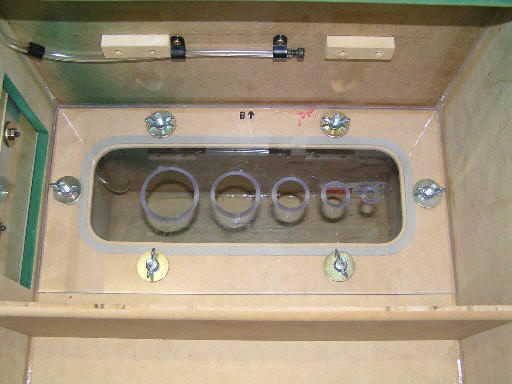
I'm not convinced that this is accurate.
I was thinking of using tubing like an annubar, and wrapping it around the legs of the table in a circle.
Thoughts?
Any pictures of your set ups would be cool.
Varnish
Re: Pressure tappings
Posted: Tue May 04, 2010 1:13 pm
by varnish
Bump
Someone must have an idea on this....come on guys.
Re: Pressure tappings
Posted: Tue May 04, 2010 9:50 pm
by jfholm
You need pressure taps for the inclined manometer to measure pressure differential. So you need on pressure tap above the measuring orifice and one below. Just put them even with the cabinet wall on the inside of the measuring chambers. The pressure tap to measure your test pressure is just under the piece being tested. Once again mine is in the corner of the upper chamber just even with the inner wall.
John
Re: Pressure tappings
Posted: Wed May 05, 2010 1:38 pm
by varnish
I've been doing some research into pressure recovery lately.
And I think there has to be a better way of finding a position for the tappings.
This links gives 3 positions for mounting pressure tappings:
http://www.engineeringtoolbox.com/orifi ... d_590.html
But it's only concerned with orifice plates in pipe systems. So its not particularly valid in our case.
I think mounting the tappings as close to the plate as possible has to be the best way.
I think that means not against the wall, but maybe floating near the orifice, like below:
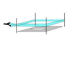
Using a y-piece to connect an annubar to the manometer. It'd just be some pvc pipe with holes drilled into it
I've also been experimenting with pressure tappings across the test piece. I have use of a blue flow bench at college.
I have connected a manometer to the top of the bore adaptor.
When I run the bench at 10" I see 12" on the manometer connected to the bore adaptor.
So the position of these tappings will make a difference.
I guess this is why I see pressures above test pressure when using the pitot tubes.
And also how I can get discharge coefficient in the 90% region.
The pressure drop isn't being measured at the restriction, but at the bottom of the bore adaptor where some of the pressure has recovered.
Re: Pressure tappings
Posted: Wed May 05, 2010 7:48 pm
by 1960FL
You want your taps to be in an area with the least possability of air movement thus preventing false readings do to impact pressure. I like to think of it as in the case of the DP taps two static pickup points on each side of the orifice plate.
Rick
Re: Pressure tappings
Posted: Wed May 05, 2010 9:11 pm
by Brucepts
Here are some pics of the pickups used in the PTS Style flowbench
Re: Pressure tappings
Posted: Thu May 06, 2010 7:15 pm
by Tony
1960FL wrote:You want your taps to be in an area with the least possability of air movement thus preventing false readings do to impact pressure. I like to think of it as in the case of the DP taps two static pickup points on each side of the orifice plate.
Rick
I agree, you want to place your pickup where the air velocity is lowest, the most obvious place is right in a corner. Averaging several different pickup points is also not a bad idea.
Re: Pressure tappings
Posted: Fri May 07, 2010 4:01 pm
by varnish
That makes sense.
Cheers Guys.